1 hardware circuit design
1.1 Non-contact IC card working principle
Non-contact IC cards, also known as RF cards, are the result of an organic combination of radio frequency identification technology, wireless communication technology and IC card technology. It solves the problem of passive and contactless card, and is convenient, fast and not easy to damage. The IC card used in this design is the Mifare One smart card from Philips. The card has a EEPROM of 8K bits and is divided into 16 sectors, each sector is 4 blocks, each block is 16 bytes, and the block is the access unit. Each sector has an independent set of passwords. And access control, with a collision mechanism, support multi-card operation, read and write distance within 10cm. The reader/writer module of the reader adopts a self-designed read/write module design scheme based on the MF-RC531 read/write chip. Data is exchanged between the read/write module antenna and the card by radio sensing. The antenna emits a fixed frequency electromagnetic wave (13.6MHz). After receiving the electromagnetic wave, the RF card generates resonance by the LC series resonant circuit that is included in the card, so that the capacitor is charged with electric charge, and then a one-way conductive electronic pump is connected. The charge is sent to another capacitor for storage, and after filtering and rectifying, a voltage of 2V is generated as a power source for the card to work. The card processes the received commands and data and returns the result to the reader.

1.2 Fingerprint recognition technology
Fingerprint recognition technology mainly includes four functions: collecting fingerprint images, extracting fingerprint features, and comparing. There are three types of equipment for fingerprint collection: optical sensors, silicon crystal sensors, and ultrasonic scanning equipment. After the grayscale image of the human fingerprint is obtained by the fingerprint collection device, image preprocessing is first performed. The main steps include pattern calculation, image enhancement, binarization, and refinement. The preprocessed fingerprint image eliminates the noise, broken lines and ridge blur of the original image, which greatly improves the image quality. Feature extraction and post processing are then performed. Feature extraction is obtained through "nodes" on the fingerprint. "Node" includes the fork of the fingerprint texture, the starting point or the coordinate position of the isolated point, and the like. Usually, a fingerprint of a person has 70 nodes. In this way, about 490 data will be generated. After processing the data, a fingerprint template is generated and stored. The size generally does not exceed 250 bytes, usually more than 100 words. Section. The fingerprint template data size fluctuates slightly due to different fingerprints.
1.3 hardware circuit design
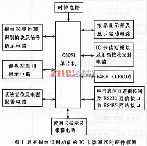
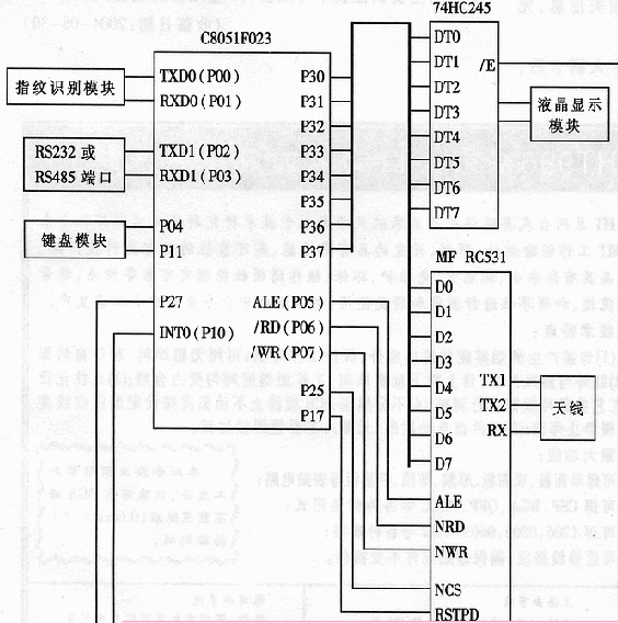
The hardware of the IC card reader with the fingerprint recognition function includes a single chip, a keyboard, a display module, an EEPROM memory, an IC card reading and writing module, a fingerprint identification module, an indication signal circuit, a host computer RS232 communication interface, an RS485 network interface, etc., such as Figure 1 shows. The motherboard circuit adopts Cygnal's C8051F023 single-chip microcomputer, which has the characteristics of compatibility with MCS-51, fast speed and rich peripheral interfaces, which can meet the needs of this design, so it is selected as the control core. The simplified circuit diagram of the motherboard is shown in Figure 2. The P3 port of the MCU is connected to the D0~D7 port of the MFRC531 chip of the read/write module, and is used as the data line between the MCU and the read/write module; the P25 is used to read and write the chip selection line of the module, and is connected with the NCS pin of the module; P17 is used for the module. The soft reset signal line is connected to the RSTPD pin of the MFRC531; the external interrupt INT0 (P10) is connected to the module interrupt request IRQ pin, and the request of the corresponding module is interrupted; the /RD and WR of the MCU read/write control are respectively connected to the NRD and NWR of the MFRC531; The address latch control ALE is connected to the ALE of the MFRC531; the P14 and P15 are respectively used to control the indicator light and the buzzer; and the P3 port also drives the liquid crystal display module with a resolution of 128×64 through the driving chip 74HC245; the P27 is used as the driving chip. Chip selection; MCU's hard serial port UART0 is connected to the serial communication port of the fingerprint identification module for control of the fingerprint identification module; the hard serial port UART1 of the MCU is used as the host computer RS232 communication port or RS485 network communication port; P04 and P11 are used as The soft serial port is used to control the keyboard module, and the power of the entire circuit board is obtained by the transformer and the DC current conversion chip to obtain 5V and 3.3V voltage.

2 Software Development
The reader software development mainly includes four parts: the development of the reader module MFRC531 application, the development of the fingerprint recognition module application, the development of the liquid crystal display program and the development of other related auxiliary circuits.
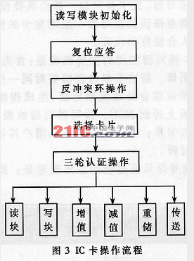
2.1 Read and write IC card workflow (1) Read and write module initialization, initialize the MFRC531 module. The corresponding register is initialized to make the module work under the ISO14443A protocol, and has ISO14443 frame and error detection function, which supports the fast CRYPTO1 encryption algorithm.
(2) Reset response, reset response operation notification module searches for MIFARE ONE card within the effective range of the antenna, and continuously issues a REQA request command. The card within the antenna range sends a response command ATQA, returns the card type code 0004, and the code returns to the MCU for card. Type recognition processing.
(3) Anti-collision ring operation. If there are multiple cards in the range of the reader antenna, it is necessary to go through the anti-collision ring and select one of the cards by the unique serial number of the card.
(4) Selecting the card operation, after successfully performing the anti-collision ring operation, according to the already obtained card serial number, a card selection operation must be performed to establish communication with the selected card.
(5) Three-round authentication operation. When accessing a fixed storage location of the card, in order to ensure the confidentiality and legality of the card operation, a three-round key confirmation process is required between the card and the reader, and all the confirmations are successful. Memory operations are confidential and legal. After the above steps, the card can be operated, and commands such as reading, writing, adding value, depreciating, re-storing and transmitting can be executed. The operation flow of reading and writing IC card is shown in Figure 3.

2.2 Fingerprint identification process and main instructions (1) Module initialization, MCU initializes the fingerprint identification module, set its working mode to command working mode, and the serial communication baud rate is 57600bps.
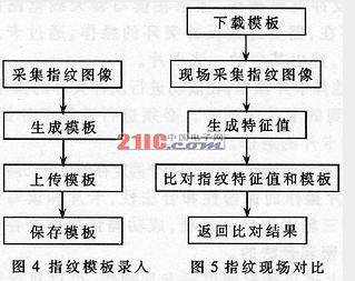
(2) Generate a template, enter the fingerprint image three times through the fingerprint sensor and generate a fingerprint template to be saved in the template buffer (Mb_Buffer).
(3) Upload module, upload the content of the template buffer (Mb_Buffer) to the MCU.
(4) Download the module and download a fingerprint template from the MCU to the stencil buffer (Mb_Buffer).
(5) Generate a feature, enter a fingerprint image through the fingerprint sensor and generate a fingerprint value, which exists in the feature value buffer (Tz_Buffer) of the module.
(6) Compare the fingerprint, compare the content of the stencil buffer (Mb_Buffer) with the feature buffer (Tz_Buffer), and give the comparison result and return it to the MCU. The fingerprint recognition program is divided into two cases: fingerprint template entry and fingerprint on-site comparison. Figure 4 and Figure 5 show the flow chart.

2.3 IC card reader application compatible with fingerprint recognition
According to different purposes, readers are mainly divided into card readers and ID readers. The card reader is generally used by the system control center card issuing office. The identity authentication reader is generally used in the terminal of the card to achieve the certification of the cardholder's legality.
The main process of the card reader application is: firstly, the fingerprint image of the user is swiped, the fingerprint collection process needs to input the same fingerprint three times, extract the feature for the three-finger fingerprint comprehensive processing, generate a fingerprint template; then upload the fingerprint template to the MCU, read and write After the fingerprint template is encrypted, the card is written into the card; finally, other relevant information of the user is written in the card to complete the card issuance process. The main process of the terminal identity authentication process is: after the cardholder swipes the card, the reader/writer decrypts the fingerprint template information stored in the card and downloads it to the template buffer of the fingerprint identification module, and then collects the cardholder fingerprint through the sensor, and fingerprint recognition. The module generates a fingerprint feature value, and stores the value in the feature value buffer of the module and compares it with the template buffer template information; the cardholder's legality is determined according to the comparison result, and other related operations can be performed after the pass. The IC card reader compatible with fingerprint recognition can be applied to an access control system requiring identity authentication, exam identity authentication, and other security authentication systems with higher security requirements.
This paper discusses the design method of an IC card reader with fingerprint recognition function. The combination of fingerprint recognition technology and IC card technology greatly improves the reliability and security of the system. An important indicator of fingerprint recognition performance is the recognition rate. The recognition rate includes two parts: FRR (rejection rate) and FAR (false rate). FRR and FAR are an inverse relationship. Weigh the ease of use and security according to different purposes, and adjust the size of these two values ​​to meet the system design needs. The reader has been successfully developed in the laboratory, stable, safe and reliable, and will be put into use in an access control system.
Bookcases And Shelves,Black Painted Bookcase,Titanium Iron Bookcase,Tempered Glass Display Bookshelf
INCHEE FURNITURE CO.,LTD , https://www.incheehome.com