Hydraulic system design of steel drum corrugator
Text / Liu Jian
Abstract: Corrugator is an indispensable processing equipment in steel drum making. The structure and working principle of the corrugator are introduced, and a corrugator hydraulic system is designed. Practice has proved that the corrugator hydraulic system works smoothly during the production process, with high synchronization accuracy and reliability.
Key words: corrugator; hydraulic system; design
The corrugation process is an important process in the middle section of the barrel. When processing the corrugation, the distance from the corrugated end to the ends is equal, and the arc around the corrugation is smooth and the height is consistent. The corrugator is located in the second process of the middle section of the 200L closed steel drum. It is located in front of the edge-trimming machine. After the reinforcement machine, the barrel after the edge is pushed to the corrugation station by the loading device, and the barrel is pulled by the left and right corrugated wheels. Clamping and embossing at both ends, thereby obtaining a plurality of corrugated projections. The corrugating machine can be combined with the ribbing machine and the edge-trimming machine to form a three-machine linkage production line, which can be fully automatic production, or can be single-process semi-automatic production by manual loading and unloading.
1 Corrugator structure
The corrugated equipment is mainly composed of left and right headstocks, corrugated wheels, bases, hydraulic stations and electronic control systems. Its structure is shown in Figure 1.
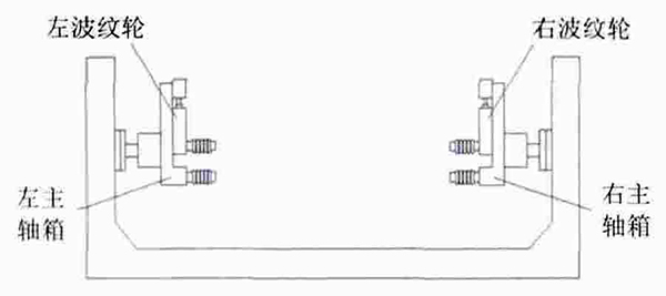
Figure 1 Corrugated machine structure
The left and right headstocks are welded structures, which drive the left and right corrugated wheels to reciprocate, and the feed hydraulic cylinder drives the travel switch to control the upper and lower limit positions. The left and right corrugated wheels are mounted on the left and right headstocks respectively. When the corrugation is pressed, the corrugated hydraulic cylinder piston rod advances. Pushing the two corrugated wheels close, clamping the module, rotating the lower corrugated wheel, bringing it to the drum to rotate, pressing out the corrugation required by the process, resetting the piston rod, and resetting the corrugated module, that is, completing the entire corrugation action. The base is a welded box structure with eight cast iron rails mounted thereon, and the left and right headstocks drive the corrugated wheels to slide on the surface of the rail. In order to make the headstock slide smoothly and smoothly, the hydraulic transmission is adopted, the action is stable, the synchronization precision is high, and the left and right headstocks and the corrugated wheel are sensitive to movement.
2 How the corrugating machine works
After loading the feeder, the left and right headstocks advance and clamp the barrel of the steel drum, and the ripple wheel has a delay of 2s. The barrel body is pushed to the corrugation station, and the left and right corrugated wheels are pushed by the feeding hydraulic cylinder to accurately press the corrugated head against the barrel body. The left and right corrugated wheels are required to be descended synchronously, and the other corrugated head is rotated to press on the barrel body. A uniform ripple. After the corrugation work is completed, the quick reset is performed in the order of return, and the barrel enters the next process.
3 Hydraulic system design
3.1 Design requirements
1) One loading hydraulic cylinder (?40/?22~685), one left and right headstock hydraulic cylinders (?50/?28~320), left and right corrugated wheel hydraulic cylinders (?100/?45 ~62) One each.
2) Feeder feeding time is 5s, left and right headstock forward time is 4s, and left and right tendon expansion time is 2s.
3) When the feeder and the left and right headstocks are operated, the working pressure is 3 MPa.
4) When the left and right corrugated wheels are in motion, the working pressure is 6.5 MPa.
3.2 Working principle of hydraulic system
Figure 2 shows the corrugator hydraulic system, which uses a stacked valve open system. The system is mainly composed of a hydraulic pump, a two-hydraulic control check valve, a one-way throttle valve, a pressure reducing valve and the like. The two-pneumatic one-way valve is used for locking each working hydraulic cylinder, and the one-way throttle valve is used for adjusting the working speed of each working hydraulic cylinder.
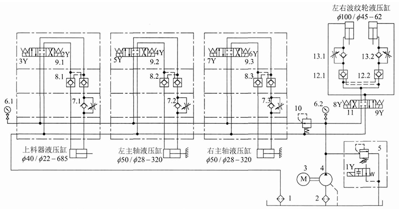
1-return filter; 2-inlet filter; 3-hydraulic pump; 4-hydraulic pump; 5-electromagnetic overflow valve; 7-one-way throttle valve;
8-hydraulic check valve; 9-electromagnetic reversing valve; 10-pressure reducing valve; 11-electromagnetic reversing valve; 12-hydraulic one-way valve; 13-one-way throttle valve
Figure 2 Schematic diagram of the hydraulic system
Table 1 shows the electromagnet operation sequence table.
Table 1 Electromagnet action sequence table
action1
2
3
4
5
6
7
8
9
Motor start
+
Feeder feeding
+
Headstock forward
+
+
Feeder returned
+
Ripple wheel drop
+
System pressure
Ripple wheel rise
+
Headstock back
+
+
The specific work flow is as follows: press the start button, the hydraulic pump starts, the electromagnet 1Y is energized, and the oil output from the hydraulic pump flows back to the fuel tank through the electromagnetic unloading relief valve 6 (the pump is idling started). The electromagnet 1Y is de-energized, the system works normally, and the hydraulic pump supplies oil to the system. The electromagnet 2Y is energized, the piston rod of the loading hydraulic cylinder is extended, the feeder is loaded; the piston rod moves to the end of the stroke, the electromagnet 2Y is de-energized, the electromagnets 5Y, 7Y are energized; the left and right headstock cylinders are piston rod extension The cylinder barrel is clamped, the piston rod of the headstock of the headstock is moved to the end of the stroke, the electromagnets 5Y, 7Y are de-energized, the electromagnet 3Y is energized; the piston rod of the loading cylinder is retracted, the electromagnet 3Y is de-energized, and the electromagnet is turned off. 9Y is energized, the left and right corrugated wheel cylinder piston rods are lowered, the piston rods of the left and right corrugated wheel hydraulic cylinders move to the end of the stroke, the electromagnet 9Y is de-energized, the system is kept pressurized, and after 2s, the electromagnet 8Y is energized, the corrugated wheel rises, left The piston rod of the right corrugated hydraulic cylinder moves to the end of the stroke, the electromagnet 8Y is de-energized, the electromagnets 4Y, 6Y are energized, and the left and right headstocks are retracted. This work cycle ends.
4 system flow calculation
The flow through several hydraulic cylinders and the system flow are calculated based on the given parameters.
1) Calculate the flow rate q1 flowing through the loading hydraulic cylinder: the piston diameter of the known hydraulic cylinder piston D1=40mm is calculated:
![]() (1)
(1)
It is known that the piston rod stroke l1=685mm, the feeding time t1=12s, the piston rod speed v1:
![]() (2)
(2)
Then the flow rate q1 flowing through the loading tank is:
![]()
2) Calculate the flow rate q2 flowing through the left and right headstock hydraulic cylinders: Know the left and right headstock cylinder hydraulic cylinder piston diameter D2=50mm, calculate the piston area A2:
![]() (3)
(3)
It is known that the piston rod stroke l2=320mm, the feeding time t2=4s, the piston rod speed v2:
![]() (4)
(4)
Then the flow rate q2 flowing through the left and right headstock cylinders is:
![]()
Calculate the flow rate q3 flowing through the left and right corrugator cylinders: Know the left and right corrugator cylinder piston diameter D3=100mm, calculate the piston area A3, get:
![]() (5)
(5)
It is known that the piston rod stroke l3=62mm, the feeding time is t3=2s, and the piston rod speed v3 is obtained:
![]() (6)
(6)
Then the flow rate q3 flowing through the left and right headstock cylinders is:
![]()
Since the two hydraulic cylinders work at the same time, the total flow of the circuit is the maximum of the flow rates of the two hydraulic cylinders. The total flow rate q of the system is:
![]()
Where k1 is the empirical coefficient; qmax is the maximum flow of the hydraulic cylinder.
5 Conclusion
According to the actual production on site, the hydraulic system of the corrugator proposed in this paper is reasonable in design, stable in performance, high in reliability, and fully utilizes the advantages of the hydraulic system. It is easy to operate and can smoothly ensure the action requirements. In the organization, the integrated oil block type structure is adopted, which makes the system have the advantages of less leakage and compact structure.
Ice Mint Toothpaste,Spry Peppermint Toothpaste,Organic Mint Toothpaste,Peppermint Flavored Toothpaste
Shenglong Co.,Ltd , https://www.sl-oralcleaning.com